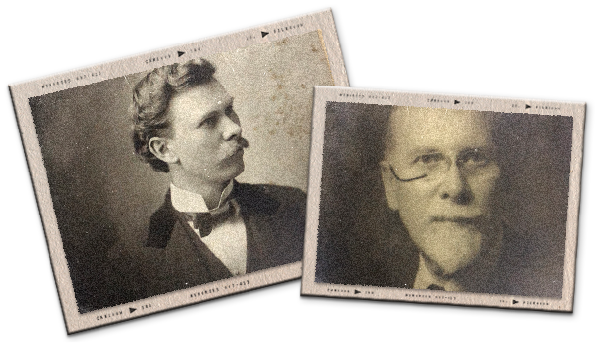
Spencer Heath's
Series
Spencer Heath Archive
Item 2089
Seven pages in pencil, breaking off three-quarters of the way through the last page. This item is shown in PDF in Item 2089a, following, in order to show the drawn Figs 1-3. Fig. 4 is not shown, nor is the material identified as “1A” which was to have been inserted in page one.
Practical Construction of Aeroplane Propellers
In comparison with the familiar marine screw the blades of which are forged or cast in a single piece of metal, the aeroplane propellers in their construction involve a great amount of intricate detail. Instead of being carved out of a single piece of wood the aeroplane propeller is built up layer by layer, the separate pieces being called “laminations.” Insert 1A The number of laminations may be from four to twelve, according to the size and design of the particular screw. In the two-bladed and four-bladed propellers the laminations may be each a single piece continuous from end to end without joints of any kind in the hub or center portion. To the use of continuous laminations, however, there are grave and serious objections, particularly in connection with two-bladed propellers, so that although this construction is quite general among European propeller makers and those who imitate them in this country, it is not the best-approved American practice. The objections to continuous laminations relate to the correct dynamic balancing of the propeller and also to the preservation of similarity of shape and equality of action under strain between the opposing blades. It is seldom that any piece of wood is of the same specific gravity throughout its length; one end is usually much denser than the other. Therefore, when the several continuous laminations for a propeller are prepared having the same thickness and outline at each end and a hole bored at the center of each, these laminations when placed together upon a round bar passing through the center holes will not even approximately balance unless the heavy ends of some of the laminations are turned about so that they are in the blade opposite to that in which are the heavy ends of the other laminations. By this arrangement of the pieces in the finished propeller it is very difficult to obtain either static or dynamic balance. This is due to the centers of gravity being somewhat differently disposed in the two blades. If the blades are geometrically opposite their centers of gravity will not be opposite. Hence the propeller will be out of balance either statically or dynamically or both according as a line joining the centers of gravity intersects the axis of rotation or not and whether that line is at right angles to the axis. If the line joining the two centers passes through the axis of rotation (the blades being of equal weight) the propeller will be in static balance about that axis, but unless this connecting line is also exactly at right angles to the axis there will be no dynamic balance and very severe vibration may result. This last condition of dynamic balance is practically to be attained only by making the laminations for each blade separately and joining them by a system of laps or double laminating of the portions which form the hubs.
The pieces for each blade lamination are gotten out in pairs (or in threes for three-bladed propellers). Great attention is paid to similarity of grain and texture of the wood so that as finally worked out each piece shall present the same “ripp sawed” or “quarter sawed” grain and appearance. A one-inch hole is provided at the center of the hub portion and each piece is carefully “weighed” by supporting the perforated hub portion on a fixed point and resting the piece on a delicate scale at about one fourth its length from the end (see Fig. 1). The scale reading in ounces is marked on each piece and those pieces having corresponding marks as to weight and otherwise similar in appearance are selected for mates.
The exterior laminations have doubly laminated hub joints as shown by Fig. 2. The interior laminations adjacent these are joined at the center as indicated in Fig. 3; these two styles of hub jointing alternating throughout the hub. Fig. 4 shows the laminations of a two-bladed propeller assembled ready for gluing.
The gluing of all parts is done in a steam heated room at a temperature of about 95 degrees F. After the separate blade laminations are weighed and matched in pairs the hub joints are prepared and glued as shown in Figures 1 and 2. The edges brought together in the joint of Figure 3 are milled with V-shaped grooves about 1/8 inch wide which mesh together in a manner that increases the amount of gluing surface by 100% over the ordinary method. When thus glued together the laminations are usually 13/16” thick. After gluing in pairs they are very finely machine dressed to ¾” and then their surfaces are further prepared for gluing by the use of toothing planes
Metadata
| Title | Article - 289 - Practical Construction Of Aeroplane Propellers |
| Collection Name | Spencer Heath Archive |
| Series | Article |
| Box number | 15:2181-2410 |
| Document number | 289 |
| Date / Year | |
| Authors / Creators / Correspondents | |
| Description | Seven pages in pencil, breaking off three-quarters of the way through the last page. This item is shown in PDF in Item 2089a, following, in order to show the drawn Figs 1-3. Fig. 4 is not shown, nor is the material identified as “1A” which was to have been inserted in page one |
| Keywords | Propellers |

